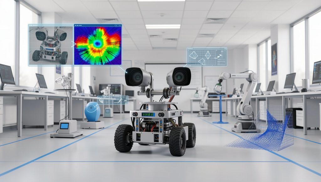
Stereo Vision Systems
Understanding depth perception and 3D vision for robotics
What Are Stereo Vision Systems?
Stereo vision is a robotic vision technique that uses two or more cameras to estimate the three-dimensional position of objects. The cameras observe the same scene from slightly different viewpoints, similar to the way human eyes perceive depth.
By comparing corresponding points in the left and right images, a robot can calculate the difference in their image positions. This difference, called disparity, can be used to estimate the distance of objects from the cameras.
How Stereo Vision Works
A basic stereo vision system contains two cameras mounted with a known separation between them. Both cameras capture the same environment from slightly different positions.
An object located close to the cameras appears at different horizontal positions in the two images. An object farther away produces a smaller positional difference.
Main Components of a Stereo Vision System
- Left camera
- Right camera
- Camera synchronization system
- Camera mounting structure
- Image-processing system
- Stereo calibration parameters
- Disparity calculation algorithm
- Depth estimation system
- Robot perception software
Stereo Camera Baseline
The distance between the optical centers of the two cameras is called the baseline. The baseline is an important parameter because it affects the depth-measurement characteristics of the stereo system.
A larger baseline can improve depth sensitivity at longer distances, while a smaller baseline can be useful when working in compact environments or at relatively short distances.
Disparity
Disparity represents the difference between the image coordinates of corresponding points observed by the two cameras.
The stereo system must identify which point in the left image corresponds to the same physical point in the right image. This process is called stereo correspondence.
Depth Estimation
After calculating disparity, the system can estimate the distance of an observed point using the stereo camera geometry.
In this relationship, Z is the estimated depth, f is the camera focal length, B is the stereo baseline, and d is the measured disparity.
This relationship shows why depth estimation depends strongly on accurate camera calibration and reliable disparity measurement.
Stereo Calibration
Stereo cameras must be calibrated before they can provide reliable depth measurements. Calibration determines the internal camera parameters and the geometric relationship between the two cameras.
Intrinsic Calibration
Intrinsic calibration determines properties such as focal length, principal point, and lens distortion parameters for each camera.
Extrinsic Calibration
Extrinsic calibration determines the relative position and orientation of the two cameras. This includes the camera rotation and translation associated with the stereo pair.
Proper calibration helps the two camera images become geometrically consistent and improves depth estimation.
Image Rectification
Stereo image rectification transforms the left and right images so that corresponding points are easier to locate. After successful rectification, corresponding features generally appear along the same image rows.
This greatly reduces the search area for stereo correspondence and can make disparity calculation more efficient.
Stereo Correspondence
Stereo correspondence is the process of finding matching points between the two camera images.
A correspondence algorithm may compare image intensity, texture, edges, or other visual features to determine which points represent the same physical location.
Reliable correspondence is easier when objects have sufficient texture. Textureless surfaces, repeated patterns, reflections, and shadows can make matching more difficult.
Disparity Map
A disparity map represents the calculated disparity for many pixels in a stereo image pair. Each valid pixel can therefore contain information about the relative depth of the corresponding scene point.
The disparity map can be converted into a depth map, allowing the robot to construct a three-dimensional representation of its environment.
Typical Stereo Vision Processing Pipeline
The left and right cameras capture synchronized images of the environment.
Lens distortion is corrected and the images can be rectified using the stereo calibration parameters.
The system searches for matching points between the left and right images.
The horizontal displacement between corresponding image points is calculated.
Disparity and camera geometry are used to estimate the distance of scene points.
The resulting depth information can be used to generate a three-dimensional representation of the environment.
Applications of Stereo Vision in Robotics
- Obstacle detection
- Autonomous robot navigation
- 3D object detection
- Robot manipulation
- Object localization
- Visual measurement
- Industrial inspection
- Depth-aware object tracking
- Mobile robot perception
- Three-dimensional mapping
Stereo Vision for Robot Navigation
Mobile robots can use stereo cameras to estimate the distance to obstacles. The resulting depth information can help the robot identify free space and plan safer paths through an environment.
Stereo vision can be particularly useful when a robot needs both visual information and geometric information about its surroundings.
Stereo Vision for Robotic Manipulation
A robot arm can use stereo cameras to estimate the three-dimensional position of an object. This information can then be transformed into the robot’s coordinate system.
For example, a vision-guided robot may identify a component on a work surface, estimate its position and depth, and move its end-effector toward the component.
Advantages of Stereo Vision
| Advantage | Description |
|---|---|
| Passive Depth Sensing | Can estimate depth using ordinary cameras without actively projecting light. |
| 3D Information | Provides spatial information that can support robot perception. |
| Longer Range Potential | A suitable camera baseline can support depth estimation over useful distances. |
| Rich Visual Data | The cameras provide normal image information in addition to depth estimation. |
| Flexible Applications | Can be used in navigation, inspection, measurement, and manipulation. |
Limitations of Stereo Vision
- Requires accurate camera calibration.
- Correspondence can be difficult in textureless areas.
- Reflections can produce incorrect matches.
- Low-light conditions can reduce image quality.
- Depth accuracy generally decreases with distance.
- Occluded areas may not have reliable stereo matches.
- Processing large stereo images can require significant computing resources.
Stereo Vision and Lighting
Lighting has an important effect on stereo matching. Adequate and relatively consistent illumination can provide stronger visual features for correspondence.
Strong shadows, overexposure, reflections, and rapidly changing illumination can make matching more difficult and may introduce errors into the depth map.
Stereo Vision vs. Single-Camera Vision
| Feature | Single Camera | Stereo Vision |
|---|---|---|
| Image Information | 2D image | Two synchronized views |
| Depth Estimation | More difficult without additional information | Can be calculated from disparity |
| Hardware | One camera | Normally two cameras |
| Calibration | Camera calibration | Individual and stereo calibration |
| 3D Perception | Limited without additional techniques | Directly supports stereo-based 3D estimation |
Improving Stereo Vision Accuracy
- Calibrate both cameras carefully.
- Keep the cameras rigidly mounted.
- Synchronize image capture when observing moving objects.
- Use appropriate camera exposure and focus.
- Provide sufficient scene texture when possible.
- Use accurate stereo rectification.
- Filter unreliable disparity measurements.
- Validate depth measurements against known distances.
Example: Stereo Vision Robot
Consider an autonomous mobile robot moving through an indoor environment. Two cameras mounted at the front of the robot capture synchronized images.
The vision system compares the images to determine disparity. Depth information is then generated for objects such as walls, boxes, furniture, and other obstacles.
The robot can combine this information with its navigation system to identify obstacles and select an appropriate path.
Conclusion
Stereo vision systems are an important technology for robotic perception. By using two cameras and analyzing the difference between their images, a robot can estimate the depth of objects and construct useful three-dimensional information.
Accurate calibration, reliable correspondence, image rectification, and effective disparity processing are essential for good stereo performance. Stereo vision can support autonomous navigation, manipulation, inspection, measurement, tracking, and 3D mapping.
Quick Quiz
1. What is the main purpose of stereo vision?
2. What is disparity?
3. Which parameter is the distance between two stereo cameras?