Required Components
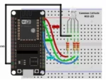
The ESP32 development board is the main controller of the project. It provides the GPIO pins needed to control the RGB LED and can also provide Wi-Fi or Bluetooth connectivity for future upgrades. The ESP32 is programmed through a computer using the Arduino IDE and a USB cable.
The RGB LED is the main output component. It contains three LED channels—red, green, and blue—which can be controlled independently to produce different colors. The 3 × 220Ω resistors are connected in series with the red, green, and blue channels to limit current and protect the LED and ESP32 GPIO pins.
A breadboard is used to assemble the circuit without soldering, making it easy to connect and modify the components. Jumper wires provide electrical connections between the ESP32, RGB LED, and resistors. The USB cable supplies power and allows program uploading from the computer.
The computer with Arduino IDE is used to write, compile, and upload the control program to the ESP32. After programming, the ESP32 can control the RGB LED by adjusting the intensity of each color channel, allowing students to experiment with different colors, brightness levels, and lighting effects.