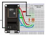
Circuit Connection
Connect the red, green, and blue pins of the RGB LED to three separate GPIO pins of the ESP32. Place a 220Ω current-limiting resistor in series with each color pin to protect the LED and ESP32 GPIO pins from excessive current.
For example, connect the red pin to GPIO 25, the green pin to GPIO 26, and the blue pin to GPIO 27, with one 220Ω resistor connected in series with each pin. These GPIO pins can then be controlled individually through the ESP32 program to produce different colors.
The RGB LED also has a common pin that must be connected according to the LED type. For a common-cathode RGB LED, connect the common pin to GND. The individual red, green, and blue pins are then controlled by applying appropriate HIGH/PWM signals from the ESP32.
For a common-anode RGB LED, connect the common pin to the 3.3V supply. In this configuration, the ESP32 controls the individual color pins by using inverted logic: a lower output/PWM value produces more brightness, while a higher value reduces brightness. This allows the three colors to be mixed to create many different colors.