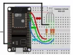
Color Control Experiment
The Color Control Experiment demonstrates how an ESP32 can control an RGB LED to create different colors by combining red, green, and blue light at different brightness levels.
Students can change the RGB values and observe how different combinations produce new colors. This simple experiment connects electronics, programming, PWM control, and the basic principles of digital color mixing.
How Color Mixing Works
An RGB LED contains three individual LED channels: red, green, and blue. The ESP32 controls each channel independently through GPIO pins. By changing the brightness of each channel, the LED can produce many different colors.
For example, turning on the red and green channels together can produce yellow. Combining green and blue can produce cyan, while red and blue can produce purple or magenta. When all three channels are set to a high brightness level, the LED can produce white light.
RGB Color Experiment
Experiment with different RGB values to discover how combinations of red, green, and blue produce new colors.
| Red | Green | Blue | Approximate Color |
|---|---|---|---|
| 255 | 0 | 0 | Red |
| 0 | 255 | 0 | Green |
| 0 | 0 | 255 | Blue |
| 255 | 255 | 0 | Yellow |
| 255 | 0 | 255 | Magenta / Purple |
| 0 | 255 | 255 | Cyan |
| 255 | 255 | 255 | White |
| 0 | 0 | 0 | Off |
The values in this experiment represent relative brightness levels. A value of 0 means that the corresponding LED channel is off, while a higher value represents greater brightness.
PWM Brightness Control
The ESP32 can use Pulse Width Modulation (PWM) to control the brightness of each RGB LED channel. PWM rapidly switches a GPIO output between HIGH and LOW. By changing the duty cycle, the apparent brightness of the LED can be controlled.
For example, a low PWM value produces a dim LED channel, while a higher PWM value produces a brighter channel. When three PWM channels are independently controlled, the ESP32 can create a wide range of colors.
This experiment is a useful introduction to GPIO control and embedded electronics. You can also explore related robotics electronics concepts through the Robotics Engineering Courses learning resources.
Experiment Procedure
- Connect the red, green, and blue pins of the RGB LED to suitable ESP32 GPIO pins through current-limiting resistors.
- Connect the common LED pin appropriately according to whether the RGB LED is common-anode or common-cathode.
- Upload an ESP32 program that controls the three RGB channels independently using PWM.
- Start with only one channel active. Test red, green, and blue individually.
- Activate two channels at the same time and observe the new colors produced by combining the light.
- Change the brightness values of the three channels and record the resulting colors.
- Try your own RGB combinations and determine which combinations produce the most interesting results.
Example RGB Values to Test
Try gradually changing the brightness rather than using only maximum and minimum values.
Green: 0, 255, 0
Blue: 0, 0, 255
Orange: 255, 100, 0
Purple: 180, 0, 255
Cyan: 0, 200, 255
Warm White: 255, 180, 100
Learning Outcomes
After completing the Color Control Experiment, students learn about:
- ESP32 GPIO pins: Students learn how GPIO pins can be used to control electronic components such as LEDs.
- RGB LED operation: Students understand that an RGB LED contains separate red, green, and blue light channels.
- PWM-based brightness control: Students learn how PWM can adjust the brightness of individual LED channels.
- Basic electronics and resistors: Students understand why current-limiting resistors are used with LED circuits.
- Arduino programming: Students practice writing and modifying programs for the ESP32.
- Color mixing using electronics: Students discover how red, green, and blue light can be combined electronically to produce different colors.
What Students Can Investigate
Students can turn this simple experiment into a small engineering investigation. They can record RGB values, observe the resulting colors, and compare how changing one channel affects the final appearance.
For example, keep the blue value at zero and gradually increase the red and green values. Students can observe the transition from red through orange and yellow toward green. Similar experiments can be performed with other combinations.
Connection With Robotics and Embedded Systems
RGB LED control is a simple example of how a microcontroller interacts with physical hardware. The same basic concept of reading or generating electrical signals is used in larger robotics and embedded systems.
Students who complete this project can continue learning about electronics, controllers, sensors, actuators, and robotics through the Educational Robot Kits resource.
GPIO is also an important foundation for connecting controllers with electronic devices. Related concepts can be explored through Common Wired Interfaces .
Conclusion
The Color Control Experiment provides a simple and engaging way to understand RGB color mixing, ESP32 GPIO control, PWM, and basic electronics. By changing the brightness of the red, green, and blue channels, students can create and investigate many different colors.
The project demonstrates an important principle of embedded systems: software instructions can directly control physical electronic components. This makes the RGB LED experiment a useful beginner project before moving toward more advanced robotics and automation applications.
Explore More Robotics Projects
Continue learning electronics, programming, automation, and robotics through Robotics Engineering Courses .