Required Components
Required Components — Wi-Fi LED Controller
| Component | Market Identity / Common Name | Typical Specification |
|---|---|---|
| ESP32 | ESP32 DevKit V1 / ESP32-WROOM-32 Development Board | 2.4 GHz Wi-Fi, Bluetooth, 3.3V logic |
| LED | 5mm LED, Through-Hole LED | Red/green/blue, 3mm or 5mm |
| Resistor | Carbon Film Resistor | 220Ω or 330Ω, ¼ watt |
| Breadboard | MB-102 Solderless Breadboard | 400/830 tie points |
| Jumper Wires | Male-to-Male Dupont Jumper Wire | 20–30 cm |
| USB Cable | Micro-USB or USB-C Data Cable | Depends on ESP32 board |
| Power Source | 5V USB Power Adapter / Computer USB | 5V output |
Component Description
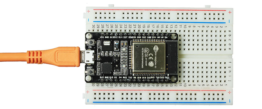
The ESP32 DevKit V1 is the main controller of the Wi-Fi LED Controller project. It contains an ESP32 microcontroller with built-in 2.4 GHz Wi-Fi and Bluetooth, allowing the LED to be controlled wirelessly from a smartphone or computer. Its GPIO pins are used to send the control signal to the LED.
The 5mm LED provides the visual output, while a 220Ω–330Ω resistor is connected in series with the LED to limit current and protect it from damage. A breadboard and jumper wires make it easy to connect the ESP32, resistor, and LED without soldering. A suitable USB data cable supplies power and allows the ESP32 to be programmed.