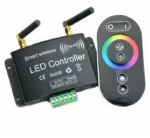
Wi-Fi LED Controller Using ESP32
The ESP32 can be programmed using the Arduino IDE to create a simple Wi-Fi-controlled LED system. The ESP32 connects to a wireless network and operates as a small web server.
A smartphone or computer connected to the same Wi-Fi network can open the ESP32 web page and use ON and OFF buttons to control the LED.
Arduino IDE Program
#include <WiFi.h>
#include <WebServer.h>
// Wi-Fi credentials
const char* ssid = “YOUR_WIFI_NAME”;
const char* password = “YOUR_WIFI_PASSWORD”;
// LED connected to GPIO 2
const int LED_PIN = 2;
// Create web server on port 80
WebServer server(80);
// Main web page
void handleRoot() {
String html = “<!DOCTYPE html>”;
html += “<html>”;
html += “<head>”;
html += “<meta name=’viewport’ content=’width=device-width, initial-scale=1′>”;
html += “<title>ESP32 LED Controller</title>”;
html += “</head>”;
html += “<body style=’text-align:center; font-family:Arial;’>”;
html += “<h1>Wi-Fi LED Controller</h1>”;
html += “<p><a href=’/on’>”;
html += “<button style=’font-size:25px; padding:15px 30px;’>ON</button>”;
html += “</a></p>”;
html += “<p><a href=’/off’>”;
html += “<button style=’font-size:25px; padding:15px 30px;’>OFF</button>”;
html += “</a></p>”;
html += “</body>”;
html += “</html>”;
server.send(200, “text/html”, html);
}
// Turn LED ON
void handleLEDOn() {
digitalWrite(LED_PIN, HIGH);
server.sendHeader(“Location”, “/”);
server.send(303);
}
// Turn LED OFF
void handleLEDOff() {
digitalWrite(LED_PIN, LOW);
server.sendHeader(“Location”, “/”);
server.send(303);
}
void setup() {
Serial.begin(115200);
// Configure LED pin as output
pinMode(LED_PIN, OUTPUT);
// Initially turn LED OFF
digitalWrite(LED_PIN, LOW);
// Connect to Wi-Fi
WiFi.begin(ssid, password);
Serial.print(“Connecting to Wi-Fi”);
while (WiFi.status() != WL_CONNECTED) {
delay(500);
Serial.print(“.”);
}
Serial.println();
Serial.println(“Wi-Fi connected!”);
Serial.print(“ESP32 IP Address: “);
Serial.println(WiFi.localIP());
// Create web server routes
server.on(“/”, handleRoot);
server.on(“/on”, handleLEDOn);
server.on(“/off”, handleLEDOff);
// Start web server
server.begin();
Serial.println(“Web server started!”);
}
void loop() {
// Process incoming web requests
server.handleClient();
}
How to Upload the Program
- Install the Arduino IDE on your computer.
- Install ESP32 board support in the Arduino IDE.
- Connect the ESP32 to the computer using a USB data cable.
- Replace the Wi-Fi name and password in the program.
- Select the appropriate ESP32 board and COM port.
- Compile and upload the program to the ESP32.
- Open the Serial Monitor and set the speed to 115200 baud.
- Note the IP address displayed by the ESP32.
- Enter that IP address into a browser connected to the same Wi-Fi network.
- Press the ON or OFF button to control the LED.
Important:
The smartphone or computer and the ESP32 should normally be connected
to the same local Wi-Fi network for this basic project.
Project Operation
The smartphone sends an ON or OFF request through Wi-Fi. The ESP32 receives the request through its web server and changes the state of GPIO 2. When GPIO 2 is HIGH, the LED turns on; when it is LOW, the LED turns off.