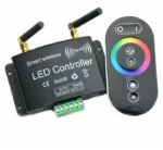
Basic Circuit
Basic Circuit
The basic circuit of the Wi-Fi LED Controller connects an ESP32 GPIO pin to the LED through a 220Ω–330Ω resistor. For example, GPIO 2 can be used as the output pin. The resistor is placed in series with the LED to limit the current and protect the LED from damage.
Connect the GPIO 2 pin of the ESP32 to one end of the resistor, and connect the other end of the resistor to the longer leg (anode) of the LED. Connect the shorter leg (cathode) of the LED to an ESP32 GND pin. The GPIO provides the control signal: HIGH turns the LED on and LOW turns it off.
When the ESP32 is powered through its USB cable, the circuit is ready for programming. After connecting to Wi-Fi, the ESP32 can receive an ON/OFF command from a web interface and change the voltage on GPIO 2 accordingly. This creates the complete control path: Wi-Fi → ESP32 → GPIO → resistor → LED → GND.